
0
Owner's of the INSTEON Thermostat INSTEON Thermostat gave it a score of 0 out of 5. Here's how the scores stacked up:

Page 12 of 28 Rev: 1/21/2014 8:35 AM
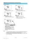
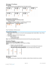
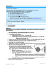
13) To ensure accurate temperature readings:
a. Carefully slide wires through provided black grommet (draft shield). See diagram.
b. Peel off protective backing.
c. Rotate to most convenient orientation for wire entrance.
14) Apply to round grommet placing indentation.
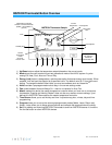
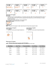
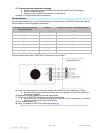
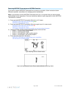
Wire Connections
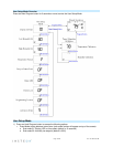
If the terminal designations on your old thermostat do not match those on INSTEON Thermostat, refer to
the chart below or the wiring diagram that follows:
Wire color from furnace/AC unit
Wire colors may vary
Function
Install on INSTEON Thermostat connector
Black or blue
Common 24V
24V COM
Red
Power 24V
24 RH
White
Heat 1
W1
Brown
Heat 2
W2
Green
Fan
G
Yellow
Cooling 1
Y1
Light blue
Cooling 2
Y2
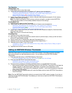
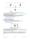
Diagram below shows inside of INSTEON Thermostat wall mount case:
15) Insert C wire into terminal C and tighten using small screwdriver (either flathead or Philips).
a. Be aware that incorrect connections may cause non-operation or Heat, Cool and Fan to
be wrongly triggered.
16) Repeat for other wires matching terminal designations.
17) Close front of INSTEON Thermostat onto back mounting plate.
a. Press firmly until you feel the connecting pins fully seat into their receptacles. You should
also feel and hear a click as the door latches.
18) Turn breaker(s) back on.
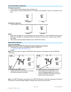
19) Allow 10 seconds for INSTEON Thermostat to boot up.
When screen displays current temperature, INSTEON Thermostat is powered and functional.


Find Your Products By Category
- Lawn and Garden
- Household Appliance
- Car Audio and Video
- Computer Equipment
- TV and Video
- Photography
- Home Audio
- Portable Media
- Automotive
- Musical Instruments & Equipment
- Communications
- Personal Care
- Marine Equipment
- Kitchen Appliance
- Baby
- Cell Phone
- Power Tools
- Video Game
- Fitness & Sports
- Laundry Appliance
- Outdoor Cooking
Please Login
